I also wanted to try a version of fins that I had seen on a few models flown. Basically you add 6 short body tubes where the fins would go. However I thought I might improve on the air resistance a little while still keeping the strength of all 6 tubes. I have seem some folks try this method with only 3 or 4 tubes but if not very firmly attached to the center tube they will be ripped off easier than normal fins since they catch so much air. I also wanted to try this method since I was really testing the ejection and just wanted a "quick and dirty" fin attachment method. I think both worked out really well for me.
The Rocket -
The rocket is approximately 110cm tall and 1.1kg without the motor. It is designed for 29mm motors and I first
flew it on one of Cesaroni's new 29mm reloads. It is made from 50mm PVC "central vac" piping. The nosecone is from an Alder
bush where I was clearing around the pond. 10mm kevlar cord and a 24in chute completes the package. Oh, and a 40mm piston
(that's quite important).
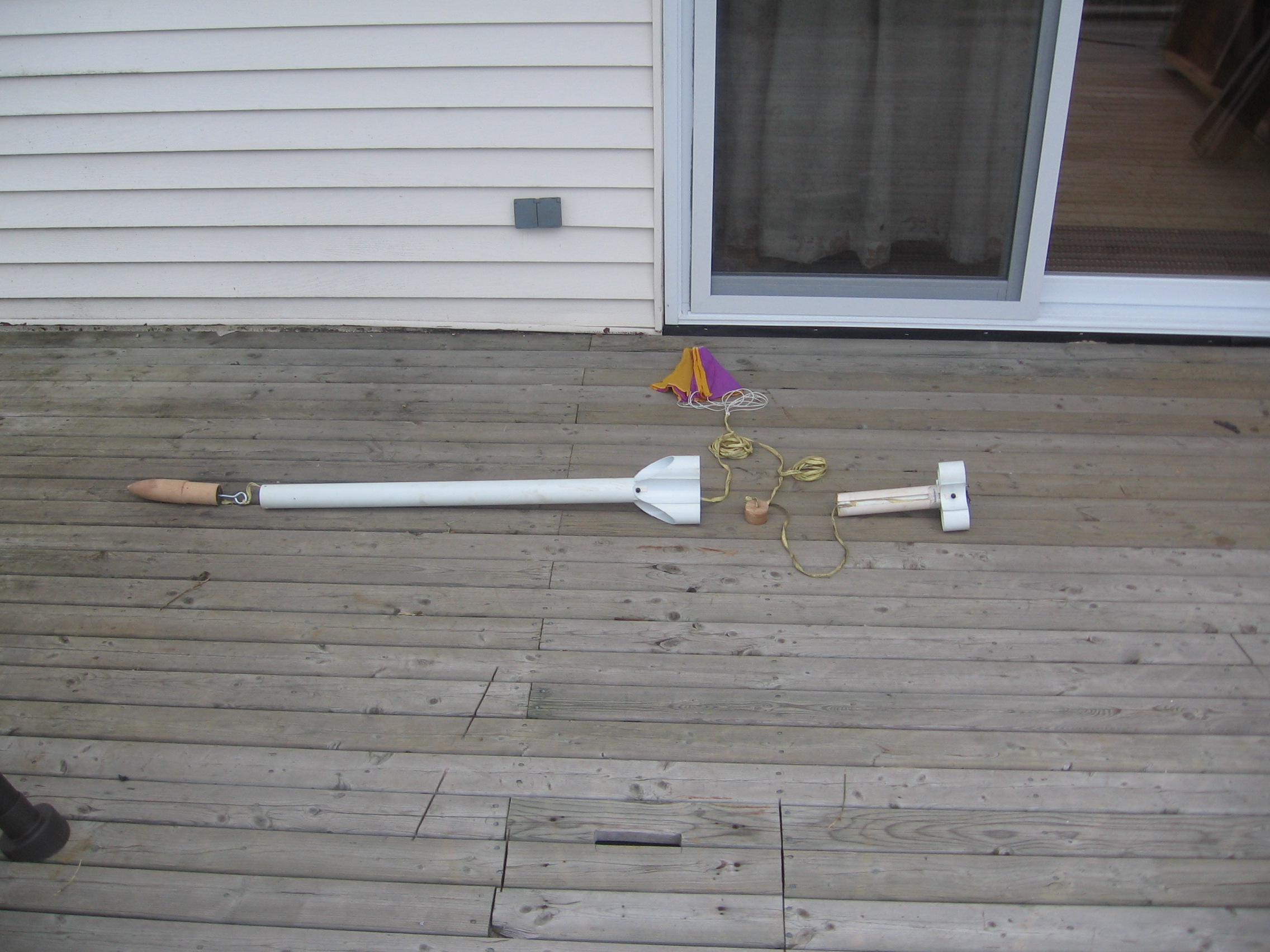
You can see from this picture that the rocket is made up of two main components. The nosecone, main fuselage and
main fins hold the parachute, piston, one launch lug and is what the motor retainer slides into. The motor retainer obviously
holds the motor but also has a subset of fins and the other launch lugs. The reason why I attached a second set of fins was
twofold. One I wanted to make sure it was stable so I wanted the extra length, but I could have just added them to the main
fuselage. The second is more important. I was afraid that the ejection charge may not blow the motor retainer out of the body
tube with enough force to get it clear out or if it did get out it might not bring the parachute with it. So I wanted to add
some air resistance so that once the retainer had been ejected it would pull the parachute with it. From what I remember of
the flight I didn't have to worry about it but I'll keep the deisign for now.

In this picture you get a better sense of how everything fits together. Two more important pieces I have not
talked about yet is the piston and the inner tube that takes up much of the space at the fore end of the main body tube. The
current design simply uses a motor ejection charge, but it could be used with an electronically activated ejection with minor
tweaking. At the fore end of the body tube I inserted another tube to act as a stop for the piston. Inside this tube contains
the parachute. I could have just glued in a ring but that just gives something for the chute to catch on, I could not have
gotten it back out if I want to try another configuration and I wanted the extra weight anyway.
So in operation the parachute goes in first, then the piston is inserted and seated up against the inner tube. The
piston is attached to the ejection cord with knots on both sides of the piston to keep it in place on the cord. When the motor
ejection charge fires it pushes the piston up against the inner tube and can go no further. Therefore the force is directed
backwards against the motor retainer and forces it out the tube. With the ejection cord attached to the motor retainer it then
pulls out the piston and the parachute with it.
I had looked at not using a piston or inner tube at all but I was afraid the force would ram the parachute so far
up inside the body tube that it would not come out. The nose cone and inner tube are held on with screws so the inner tube can
be removed and other configurations used if I want to experiment on something else.
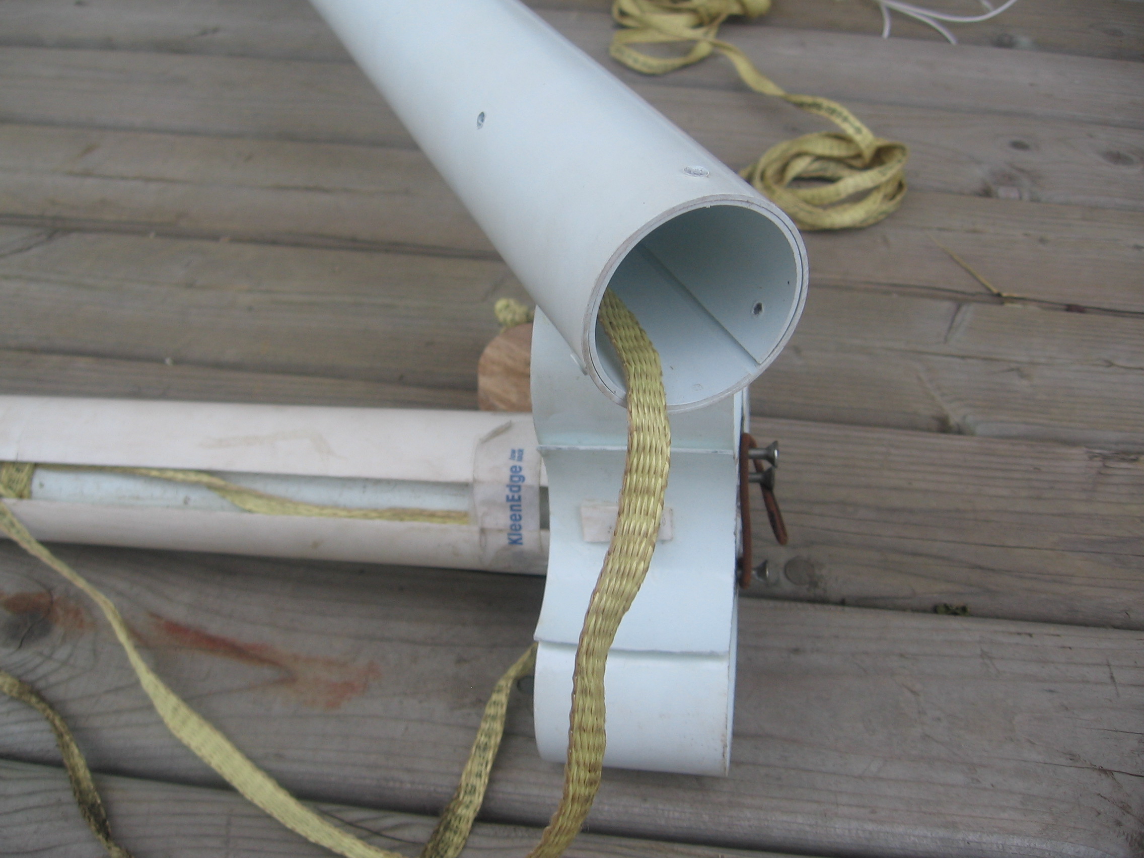
This picture shows more of a close up of the motor retainer and bottom fin profile. Since I'm using PVC I had to
do a bit of jiggery-pokery to build the motor retainer, so I won't go into details. The basic concept for the retainer is that
it has to keep the motor from ejecting from the retainer (duh) while allowing the retainer to be ejected from the rocket. It
must also attach to the parachute somehow. This leaves many other configurations to the imagination.
This picture shows the split body tube that I used as the inner tube at the fore end of rocket. It comes down to
within about 4 inches of the retainer. You can also see the small hole I put in the fore section to allow pressure to equalize
within the upper tube. I have no idea if I need it or not but I put it in just in case.
Further considerations -
Although the concept sounded pretty sound to me I did have some concerns. One of the main ones was whether the
retainer would stay in the rocket once burnout occured. While the motor is burning the retainer tube will push the whole
rocket forward and everything stays together. Even if the retainer rotates and the fins are not lined up it should still
remain stable. However during the coast phase if the motor retainer does rotate it may catch enough air to deploy early.
Although this did not happen on the short flight I have tried, I will have to watch for this on longer flights.
The opposite is also true. I have to be careful not to have the retainer so tight so it will not deploy. Since
the retainer is so long it has much further to go than a nose cone or mid tube deployment.
As I said earlier one of the reasons I got into this was to see if I could develop a rocket with no nosecone nor
mid point seam. This necessitates some kind of motor ejection recovery. I am still working on refining this method to be rid
of the forward tube, piston and retainer all together. With an electronic ejection, a mid tube ring and a ring to attach a
shock cord to on the fore end of a motor I think you can reduce the weight and air resistance (no seams) of a rocket.
Finally here is a picture of the next project, made from 3in PVC. I hope it will get me my TRA L2, CAR L3. I have only just started
it and you can see that the nosecone has just been glued up. Where the first model wighed in at less than 2.5lbs and could
only use 29mm motors, I expect this one will weigh in at more than 12lbs and be able to run 38mm or 54mm motors.
I'm still waiting on some inflight pictures, so I'll post them when I get them.